

Welcome to The Learning Pathway.
Join me on my journey to discover the mechanics of learning through the perspective of a mechanic - an automotive mechanic.
What if we focused on our learning skills as we do our hobbies and jobs?
What if we could get on the road to becoming an expert learner?
Feb. 13, 2010
I believe, if you really want to learn something, being able to take it apart and put it back together is a good start. Considering the time I have spent working with lab scopes, sooner, or later I would disassemble a waveform.
What I found is that there are a few ways to do it. For example, one method deals with the actual actions that shape the waveform. (I will go over this method in a different article.) Another, the one chosen for this article, reveals a functional framework of what a waveform is all about.
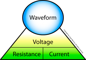
My goal, as usual, was to build a graphical representation of the assembly that makes up a waveform. Accomplishing this means identifying the functional building blocks. Of course, as a mechanic, I take the mechanics approach and start taking things apart.
Starting with the waveform as the focal point, there are two pathways for disassembly of the waveform system: Via the parts that lead to where the waveform comes from and the parts that lead to where it goes.
In the following links, I will take you step by step in both directions. First, we will go against the natural flow of the system, starting at the waveform and going down through the parts make up the waveform. Then, we will follow the natural flow of the system information from the waveform up.
So, what value is this? For one, I see it as an excellent way to exercise my mechanical skills beyond the nuts and bolts. Two, this type of "find the functional building blocks" mechanical tear down creates a framework that can be used as a foundation to work from. For example, as a result of this framework, I was able to build a more thorough and effective framework approach for waveform analysis!
When I approach a waveform I do so with 5 locked and loaded questions:
Questions 1 and 2 are about reading the waveform. The others deal with unexpected occurrences.
If the unexpected is a "controlled" issue, then the path to follow is that of the system information. For example, an injector stays at 2 mS during an attempt to accelerate.
For a waveform shape problem, I then return to the waveform framework. The questions become:
What changed the waveform?
What changed the VRI relationship?
What causes components to change?
The next step is to pinpoint the exact source. This story continues and leads to what I call, Building a Waveform – Ohm's Law II. Keep an eye out for a future article.
|
A waveform is a line graph of voltage changes over time. A waveform, as displayed on a lab scope, is the result of the difference in voltage between the circuit test points of the red and black test leads. |
|
Powered by Hackadelic Sliding Notes 1.6.5
|
If the waveform voltage level changes, then the relationship of the voltage, current and/or resistance changed within the circuit.
|
 |
Powered by Hackadelic Sliding Notes 1.6.5
Powered by Hackadelic Sliding Notes 1.6.5
Powered by Hackadelic Sliding Notes 1.6.5
Powered by Hackadelic Sliding Notes 1.6.5
You must be logged in to post a comment.